
%20(2).svg)

Wi-Fi Module Architecture Options
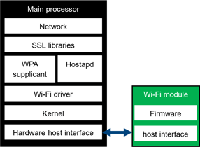
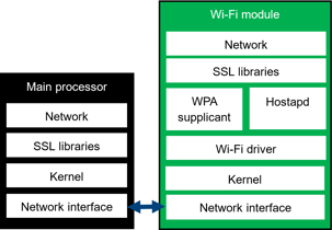
When integrating a Wi-Fi station module into an embedded device, there are two architecture options: hostless and hosted. The conceptual differences between these approaches are illustrated in the figures below.
The primary distinction is where the Wi-Fi software stack resides. In a hostless module, the Wi-Fi-related software stack is integrated within the module itself. In a hosted module, the Wi-Fi software stack runs on the host processor.
Hostless vs. Hosted Modules
Hostless Module
The main advantage of a hostless module is its simplified integration. Because the Wi-Fi functionality is self-contained within the module, the host processor requires minimal Wi-Fi-specific software development. This approach can significantly reduce development effort and shorten time-to-market.
Hosted Module
In a hosted architecture, the Wi-Fi software stack must be integrated into the host processor's software or firmware. Although this increases development and verification effort, it provides greater flexibility for feature customization, performance optimization, and long-term maintenance throughout the product lifecycle.
| Hosted module | Hostless module |
 |
 |
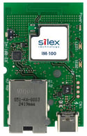
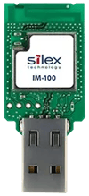
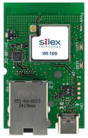
Example: Silex Wi-Fi 6 Hostless Module IM-100
The IM-100 is a Wi-Fi 6 hostless module that supports a 1×1 antenna configuration with a 20 MHz channel bandwidth, providing a Wi-Fi PHY data rate of up to 143 Mbps.
To connect with the host processor, the IM-100 provides:
- 100 Mbps Ethernet
- USB 2.0
- UART
When Ethernet or USB is used, practical TCP/UDP throughput is typically 40-50 Mbps after accounting for Wi-Fi, network, and interface protocol overhead. When UART is used, achievable throughput is limited by the selected UART baud rate.
The table below summarizes the network interfaces supported by the IM-100. Silex also offers derivative versions of the IM-100 that are optimized for specific host interfaces.
|
Product Name |
Interface |
Requirements for a main processor/hardware design |
|
IM-100 |
Ethernet (RMII/MDIO) |
Network stack over Ethernet Ethernet PHY (optional) AT command serial port for IM-100 configuration Flash memory for IM-100 firmware |
|
USB 2.0 |
Network stack RNDIS stack USB D+/- (optional) AT command serial port for IM-100 configuration Flash memory for IM-100 firmware |
|
|
Serial (UART) |
AT command serial port Flash memory for IM-100 firmware |
|
|
IM-100-EB |
Ethernet (MDI) |
Ethernet connector Network stack over Ethernet HTTPS stack for device configuration |
|
IM-100-RB |
USB 2.0 |
USB Std-A connector Network stack RNDIS stack |
|
IM-100-SB |
Serial (UART) |
B to B connector AT command serial port |
|
Antenna |
IM-100 |
IM-100-EB |
IM-100-RB |
IM-100-SB |
|
MHF-1 (u.FL) connector |
|
|
Contact us |
|
|
RF Pad (IM-100)
PCB antenna |
|
|
|
- |
_150x150.png?width=125&height=117&name=IM-100(MHF)_150x150.png)
.webp?width=125&height=136&name=IM-100-SB-Front%20(1).webp)
_150x150.png?width=125&height=117&name=IM-100(PAD)_150x150.png)