
Today, I will write about basics of Bluetooth Classic specification. We will find an answer to simple question from the specification that who or what decides Bluetooth (ACL) frame type. In this article, I will refer to original bluetooth specification document like “Vol.2 Part.B …” from the Core Spec 4.2 unless noted otherwise.
ACL Frame Type
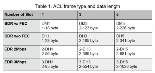
Bluetooth Classic defines ACL (Asynchronous Connection Less) for general data frame and SCO (Synchronous Connection Oriented) for synchronous audio frame. ACL has two frame types, DM (which provides Forward Error Correction:FEC) and DH (which doesn’t provide FEC). In addition to these, the number is appended to these frame types like “DM1” or “DH3” to indicate
how many 625 usec. “slot” will be occupied. In EDR (Enhanced Data Rate) introduced with Bluetooth 2.0, DH frame got double and triple the data rate mode denoted like “2-DH1” or “3-DH5”. All these ACL frame types defined in Vol.2 Part.B 6.5.4 are summarized in Table 1.
Which protocol layer and what decide these frame types, you ask?
Can we request 3-DH5 frame if we want to communicate at highest data rate available? If possible, how?
Bluetooth specification does not offer clear answer to this simple question. Instead, it just show hints that will lead you to the ultimate answer. This is natural aspect of “specification”, but I think it is one of the factor that makes it difficult to start learning Bluetooth.
.
Relationship Between L2CAP and ACL
First hint is Section 7.2 “Fragmentation and Recombination” in Vol.3 Part.A “Logical Link Control and Adaptation Protocol (L2CAP)”. Figure 7.2 of this section (see below) shows diagram of data path starting from L2CAP layer and ending up wireless packet. Data transfer request sent to L2CAP layer is broke into multiple HCI packet and sent out to hardware (Bluetooth chip.) Firmware (Embedded Software) reassemble packet, re-split into multisegment frame and transmit these as wireless packet.
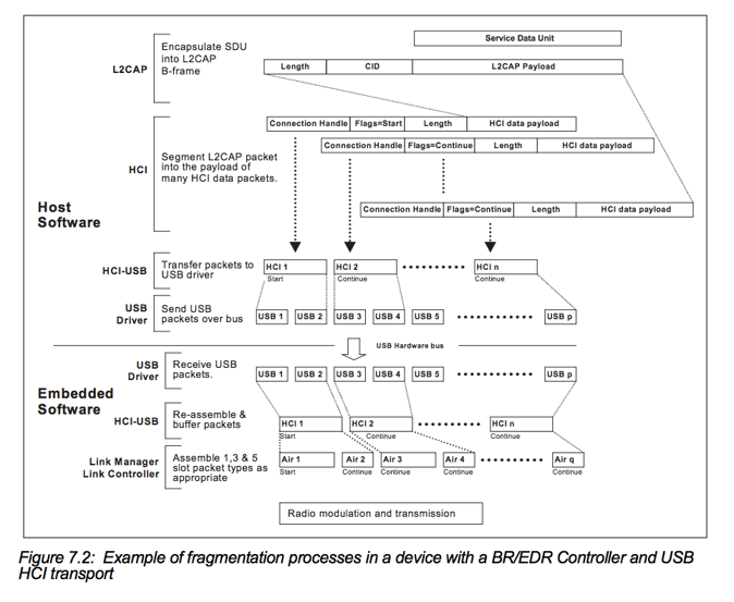 From this figure, we can also see that HCI and wireless packet do not map one-to-one, single HCI packet can be split into multiple wireless packet, and these operations are executed in Link Manager Link Controller layer. The specification indicate that this layer can select packet type by only saying “Assemble 1, 3 & 5 slot packet type as appropriate” but it doesn’t clearly specify what is “appropriate”. Regardless of vague selection logic, we can say that “chip firmware select ACL frame type. Upper layer doesn’t seem like doing it” at this stage.
The details of HCI packet are specified in Vol.2 Part.E 5.4.2 HCI ACL Data Packets. The parameters passing down from HCI layer are Connection Handle, PB Flag, BC Flag, Total Length, and Data only. These doesn’t include frame type. Again, we can reconfirm that we can’t specify ACL frame type at HCI level with this fact.
But it does not necessarily mean that upper layers have to have chip dictate Bluetooth ACL frame selection process and give up control at all. The specification give us couple of ways to control it. Although, this “couple of ways” are scattered around the specification. Again, it makes deciphering the specification difficult.
First, Vol.2 Part.E 7.1.5 Create Connection Command. This is a command sent along with L2CAP connection establishment, it is corresponding to socket connect of TCP. In reply, Connection Complete event return Connection_Handle which can be used with HCI ACL Data Packets. Create Connection Command has 16 bit parameter Packet_Type (Table 2).
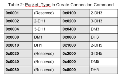
Packet_type is bitmask of frame types that allowed to use. From the specification,
“The Packet_Type command parameter specifies which packet types the Link Manager shall use for the ACL connection. When sending HCI ACL Data Packets the Link Manager shall only use the packet type(s) specified by the Packet_Type command parameter or the always-allowed DM1 packet type. Multiple packet types may be specified for the Packet Type parameter by performing a bit-wise OR operation of the different packet types. The Link Manager may choose which packet type to be used from the list of acceptable packet types.”
From here, we can tell one of the condition to determine frame type that was said “as appropriate” in Vol.3 Part.A 7.2 is that “the frame must match to the type specified with Packet_type bitmask passed along from upper layer when connection establishment,” but “DM1 must always be available.”
The command hciconfig <hci> ptype of Linux BlueZ show the “list of packet type” and can specify the “list of packet type” with comma connected strings like hciconfig <hci> type DM1,DH1,DM3,… But document (man hciconfig) doesn’t clearly explain its purpose nor how can it be used. To tell the truth, this ptype carries the parameter which is set to the bitmask of Create Connection. The hciconfig command pass this parameter to Linux Bluetooth stack with ioctl HCISETPTYPE, the stack record it to HCI unique data member hdev->pkt_type. While establishing the connection, this value is copied to connection unique data member conn->pkt_type, then it is copied to the parameter data structure cp.pkt_type (after converted to little endian,) and finally, given to the chip through HCI.
That makes sense, now we know there is the mechanism to specify frame type. But the story won’t end here, this is why Bluetooth never comes easy.
ACL BDR and EDR
Packet_Type mask can specify both frame type in BDR and EDR respectively, but Bluetooth specification does not allow mix and send BDR and EDR frames to communication channel at the same time. Bluetooth frame format is defined in Vol.2 Part.B 6.4, TYPE field has 4bit, so it can express 16 types of frame. For ACL(BDR), 4 types are assigned (NULL, POLL, FHS, DM1) and DH1, AUX1, DM3, DH3, DM5, DH5 is assigned to the other 12 types. Therefore, remaining 6 types should be able to comfortably accommodate EDR’s 2-DH1/DH3/DH5, 3-DH1/DH3/DH5 but Bluetooth SIG didn’t take this route when they extend EDR for some reason. They introduced parameter called “PTT” to reserve existing BDR assignment and switch to new EDR assignment (Table 3).
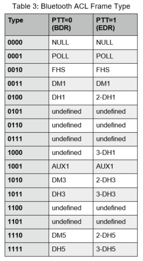
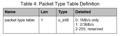
PTT is an abbreviation of Packet Type Table, its values are defined in Vol.2 Part.C 5.2 LMP Parameter Definitions (Table 4).
But I have already shown, an argument of Create Connection Command doesn’t have PTT value. PTT is the parameter get along with baseband link (inter MAC address connection), not the one can be set for each logical link (≒L2CAP connection.)
Then, saying who or what set PTT and how, LMP_packet_type_table_req (Vol.2 Part.C 4.1.11) takes care of it. The node wanting to use EDR publish LMP_packet_type_table_req with PTT=1, and if it is responded with LMP_accepted_ext, ACL packets exchanging between the node will be switched to PTT=1’s EDR except DM1. This switching is applied to not only new L2CAP connection opened hereafter but also existing L2CAP connection already established because this switching is happening in “baseband link” (SCO for synchronous audio has different mechanism from ACL to switch between BDR/EDR.)
But it looks like inconvenient mechanism, isn’t it? If RF condition deteriorate and error rate was increased after switched to EDR, the node can’t try to improve the error rate by dropping to BDR modulation to use DH3 or DH5 BDR multi-slot frame. Instead, it must down all the way to DM1. To use DH3 or DH5, the node have to re-negotiate with PTT=0 with LMP. If RF condition improved and the node want to use EDR, it must switch to PTT=1 again.
I do not understand why this design is employed to Bluetooth that should have been considering mobile use and ACL BDR frame type has opening area where EDR could fit in. While standardization process, they may have thought EDR will become de-facto standard that make BDR obsolete, or they should not use up all 4 bit 16 types as they may develop Super EDR mode and need more frame type in the future.
In reality, their Bluetooth Classic PHY rate improvement had stopped at EDR, for further improvement they planned outside of Bluetooth band (UWB or PAL/AMP) but never see the light, Bluetooth 5 LE regarded EDR as if it “did not exist” and employed 2Mbps GFSK. These sort of stories may be the “one of the kind” as usual.
Forgotten Features of LMP
By the way, Bluetooth has two more frame selection mechanism. The one is LMP Channel Quality Driven Data Rate Change (Vol.2 Part.C 4.1.7), the other is LMP Control of Multi-slot Packets (Vol.2 Part.C 4.1.10). Both of these are pretty old command that exists since Bluetooth 1.0.
I will start with relatively simple Multi-slot Packets. It has two commands, LMP_max_slot and LMP_max_slot_req, originally the former meant “allowance of maximum number of slot from master to slave”, the latter “request of maximum number of slot from slave to master.” Bluetooth 1.2 and later expand its interpretation, removed a limitation of master/slave, into “allowance of maximum number of transmittable (therefore receivable to itself) slot from remote node” and “request of maximum number of slot the node wanting to send.” Because default number of slot is defined to be 1, the node only can transmit DM1/n-DH1 right after established the baseband link, multi-slot frames like DM3 and DM5 can be used after LMP_max_slot was exchanged.
LMP_max_slot only “allow” it, final call on the transmit frame type is left to the chip of remote node. The command “allow remote node sending DM5/DH5” but can’t request remote node to “keep sending with DH5 even if RF condition is not good.” Channel Quality Driven Data Rate Change (CQDDR) realize this request.
CQDDR consists of two commands, LMP_auto_rate (no parameter) and LMP_preferred_rate (with 8 bit data_rate parameter). LMP_auto_rate command indicate “you can select frame type as you like” (usually the default), while LMP_preferred_rate is the command that indicate “please use this (or these) frame type as much as possible.” However, it is not mandated since it is merely “preferred.”
Originally in Bluetooth 1.0, data_rate had only two types, 0: medium rate (with FEC = DM) and 1: high rate (without FEC = DH), it is practically positioned as the command to ON/OFF the FEC. Bluetooth 1.2 added meaning to upper bit, so the number of slots[1] can be specified by bit1-2, so that you can instruct to “use DH5 as much as possible.” In Bluetooth 2.0, upper bit got more meanings, bit3-4 became EDR bit rate (0=DM1, 1=2Mbps, 2=3Mbps), bit5-6 did EDR number of slots. But coming this far, I want to say “I don’t understand what you are going to achieve.” It is even more, if I combine specification mentioned above that we can’t switch EDR/BDR unless PTT is exchanged with LMP every time we need to.”
Summary
In summary, transmit frame type selection of Bluetooth Classic ACL is:
- Basically, determined at the sole discretion of Bluetooth chip. There is no mechanism to indicate frame type from upper layer.
- Upper layer can specify mask of frame type with PTYPE parameter when establishing ACL connection. However, DM1 is always enabled regardless of specified mask.
- EDR 2Mbps and 3Mbps modes can’t be used unless PTT=1 is exchanged (LMP_packet_type_table_req) between baseband. And after PTT=1 is established, frame type definitions are overwritten, ACL BDR packet except DM1 can’t be used after this point.
- Multi-slot packet like DM3 and DM5 can’t be used until baseband mutually agree (LMP_max_slot) with each other.
- You can indicate frame type to remote node. But it is “as much as possible”, not mandated. CQDDR also an indication to baseband, but you can’t specify for each connection.
As a natural consequences, it sounds easy to understand once you get it, it actually was challenging to decipher Bluetooth specification. As long as lightly searching through the net, I could not find this kind of explanation, just “transmitting frame type is selected by link manager” at its best, but no such page mentions that this “link manager” sits not in LMP but in Bluetooth chip firmware, and LMP come into play with Max slot and Preferred rate (halfway through.)
This had been long standing questions since I started Bluetooth development, but I finally was able to get some clarity this time around.
Additional Resources:
Application Note: How to Implement Bluetooth on the NXP i.MX6 Sabre-SD EVK using the SX-SDMAN
White Paper: Realizing the Dream of Wi-Fi Everywhere, All the Time